LTE employs a new network architecture made up of multiple Evolved Packet Cores (EPCs) that communicate with each other and with evolved universal terrestrial radio access network base stations (eNBs). Each EPC contains a Mobile Management Entity (MME) and a System Architecture Evolution Gateway (SAE). The eNB stations communicate with the EPCs, with each other, and with user equipment (UE).
Click Downlink in the tree view to open the Downlink node. The Downlink node enables you to set parameters of the cell, reference signal, and synchronization signals.
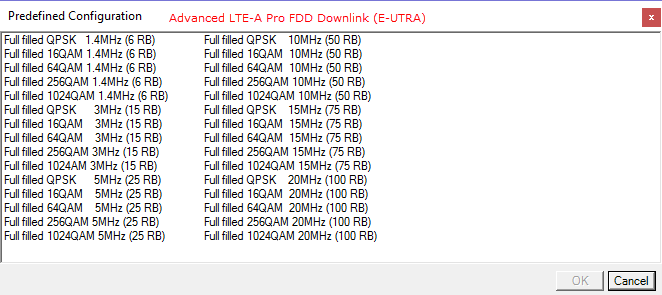
Opens a ![]() dialog box
from which you can select a base channel configuration.
dialog box
from which you can select a base channel configuration.
Opens the DL FRC Wizard where you can set up a fixed reference channel (FRC).
Range: 0 to 503
Default: 1
Enter a value for the Cell ID. The software sets the values in the Physical Layer Cell ID Group and Physical Layer Cell ID Sector cells based on the entry. Cell ID = [(3 x Physical Cell ID Group) + Physical Cell ID Sector]. See 3GPP TS 36.211.
This property is also available in the Carrier Aggregation node.
Range: 0 to 167
Default: 0
The software sets this value based on the Cell ID entry. Cell ID = [(3 x Physical Cell ID Group) + Physical Cell ID Sector]. (See 3GPP TS 36.211.)
Choice: 0 | 1 | 2
Default: 0
The software sets this value based on the Cell ID entry. Cell ID = [(3 x Physical Cell ID Group) + Physical Cell ID Sector]. (See 3GPP TS 36.211.)
Range: 0 to 2
When you set the value in the Physical Layer Cell ID Sector cell, the software sets the Number of Orthogonal Sequence to the corresponding value. (See 3GPP TS 36.211.)
Choice: 1.4 MHz (6RB) | 3 MHz (15RB) | 5 MHz (25RB) | 10 MHz (50RB) | 15 MHz (75RB) | 20 MHz (100RB)
Default: 5 MHz (25RB)
Double-click or use the drop-down menu to set the system bandwidth and number of Resource Blocks (RB). When you select a system bandwidth, the software automatically adjusts the value in the Total number of Resource Blocks cell and the Total number of Occupied Sub-carriers cell.
When the System Bandwidth is decreased, the DL-SCH Tx Sequence window's RB size, and some of the other data channel's settings, are reconfigured, similar to when a Predefined Configuration is executed. But, when the System Bandwidth is increased, no change to the DL-SCH Tx Sequence window's RB size, or the other data channel's settings occurs.
Refer to 3GPP TS 36.211.
Choice: 1 Antenna | 2 Antennas | 4 Antennas | 8 Antennas
Default: 1 Antenna
Specify the total number of base station antennas.
For multiple signal generator configurations, set the Channel State parameter in the Fading section of the Carrier node to On to make this cell active. When the channel state is off, you must change the number of signal generators (for example, use a Quick Setup) to change the number of BS antennas.
This parameter indicates the total number of physical antenna port configuration used for downlink transmission in this cell.
Total number of Antennas and Number of CRS Antenna Ports determines the resource elements that are reserved for Cell Specific reference signals.
Total number of Antennas and Number of CRS Antenna Ports are different parameters and are available to set respectively.
Refer to 3GPP TS 36.211 and 36.311.
Range: 0.00–100
Default: 0.5
Enter a value that specifies the distance between the antennas. The value is specified in wavelengths units of the center frequency for the corresponding Component Carrier. Use this setting when generating a beamforming signal.
Choice: 0 | 1 | 2 | 3 | 4 | 5 | 6 | 7
Default: 0
In multi-antenna configurations, specify the antenna to be used for transmitting the downlink signal. The available selections are determined by the Total Number of Antennas setting.
Refer to 3GPP TS 36.211.
Choice: Total Power | RSTP
Default: Total Power
Double-click or use the drop-down menu to select the power definition type for the primary cell.
The power definition type for secondary cells is automatically set same type of the primary cell and set the value as read-only.
In multiple carrier case, Power Definition Type parameter in each carrier should be same.
If Total Power is selected, power reference is Amplitude parameter on Instrument node. In single/multiple carrier and Total Power case, RSTP and OSTP are automatically calculated by Amplitude parameter on Instrument node, Power parameter on Component Carrier and each carrier signal settings.
If RSTP is selected, power reference is RSTP. In single/multiple carrier and RSTP case, Amplitude parameter on Instrument node, Power parameter on Component Carrier and OSTP are automatically calculated by RSTP and each carrier signal settings. In this case, Power parameter on Component Carrier is set read-only.
If uplink and downlink carriers are mixed as multiple carrier, correct RSTP calculation is not available.
Range: -15.00 to -144.00 dBm
Default: -40.79 dBm
Enter the Reference Signal Transmit Power in dBm, when the Power Definition Type is RSTP. Otherwise displays the Reference Signal Transmit Power in dBm and the value is updated after generation.
In the case Power Definition Type is Total Power, RSTP is automatically calculated by Amplitude parameter in Instrument, Power parameter in Component Carrier and each carrier signal settings.
In the case Power Definition Type is RSTP, Amplitude parameter in Instrument and Power parameter in the Component Carrier is automatically calculated and set the value as read-only.
Available setting range and step depends on hardware.
See 3GPP TS 36.141 for more information.
Display the Downlink OFDM Symbol Transmit Power in dBm. This parameter is set by the software.
For detailed information about OSTP, refer to 3GPP TS 36.141.
The value in this cell is set by the software based on the System Bandwidth setting.
The value in this cell is set by the software based on the System Bandwidth setting. The center subcarrier is not used for downlink transmission, so the number of transmitted subcarriers is one less than the number of occupied subcarriers.
Default: 15 kHz
Displays the subcarrier spacing for the downlink. Only 15 kHz spacing is available in this release.
Choice: Normal | Extended
Default: Normal
Double-click or use the drop-down menu to select a Normal or Extended cyclic prefix. The software sets the Number of Symbols for Resource Block based on the cyclic prefix selection.
Default: 12
Displays the number of consecutive subcarriers in a downlink resource block.
Default: 7 for Normal Cyclic Prefix; 6 for Extended Cyclic Prefix
Displays the number of consecutive OFDM symbols in a downlink slot.
Choice:
CE Mode A: 1 | 2 | 4 | 8
CE Mode B: 2 | 4 | 8 | 16
Enter the number of consecutive absolute subframes for narrow band. This parameter is used only when UE Type is set to BL/CE.
See 3GPP TS 36.211 and 331 for more information.
Range: 0 or 1 with comma separated input
Length:
Valid Subframe Size 10: 10
Valid Subframe Size 40: 40
Default: 1, 1,..., 1, 1 (all 1)
Specify a set of valid subframes for BL/CE UE.
Value 0 in this bitmap indicates that corresponding subframe is invalid for transmission.
Value 1 in this bitmap indicates that corresponding subframe is valid for transmission.
This parameter is applicable only when UE Type is set to BL/CE.
A bit of Valid Subframes used for Absolute Subframe Number should be 1 when UE Type is set to BL/CE and PDSCH or MPUCCH state is on. Otherwise, an error occurs during the generation.
Choice: 10 | 40
Default: 10
Double-click or use the drop-down menu to select Valid Subframes Size.
Range:
System Bandwidth > 1.4 MHz: 1 to 3
Otherwise: 2 to 4
Default: 3
Enter the OFDM starting symbol for MPDCCH and PDSCH except the PDSCH carrying SIB1-BR.
This parameter is applicable only when UE Type is set to BL/CE.
For each PDSCH subframe carrying SIB1-BR, regardless of this parameter, the OFDM start symbol of each subframe uses 3 for 1.4 MHz system bandwidth, otherwise 4.
See 3GPP TS36.213 and 36.331 6.2.2 for more information.
Choices: On | Off
Default: Off
Set whether to use ABS (almost blank subframe) for each component carrier by clicking the cell and then the drop-down arrow ![]() to make the selection:
to make the selection:
|
|
Off |
|
ABS is disabled and its related settings are inactive (nothing shows). |
|
|
On |
|
ABS is available for the component carrier, and its related settings are active. |
When the component carrier ABS state is on, the Transmission Configuration Length for all DL-SCH becomes a read-only value that is set to the same length as the Waveform Generation Length.
This property is also available in the Carrier Aggregation node.
Default: 40-bits all 0
Coupling: Inactive until ABS is On
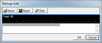
Set the ABS bit pattern for the corresponding component carrier by clicking the cell and then the dialog box button  . This launches the
 ![]() Bitmap Edit dialog box that is used to enter up to 40-bits.
Bitmap Edit dialog box that is used to enter up to 40-bits.
Each bit position represents a subframe. Use the keyboard to enter either a 0 or a 1.
|
|
0 |
|
ABS is not applied to the subframe. |
|
|
1 |
|
ABS is applied to the subframe. |
Within the Bitmap Edit dialog box are the two buttons Import and Export:
Import allows the loading of a previously saved bitmap.
Export allows the saving of the current bitmap.
The first position of the ABS pattern corresponds to subframe 0 where SFN = 0. The ABS pattern is continuously repeated during the Transmission Configuration Length of the DL-SCH. For example, if the Transmission Configuration Length is 120 ms and there are 30-bits in the ABS pattern, the ABS bit pattern would repeat four times.
Per the 3GPP standards, ABS is designated as protected from inter cell interference from the sending eNB.
This property is also available in the Carrier Aggregation node.
Choices: On | Off
Default: Off
Coupling: Inactive until ABS is On
Click the cell to show the drop-down arrow ![]() that when clicked displays the choices to either enable or disable PSS/SSS during the ABS for the corresponding component carrier.
that when clicked displays the choices to either enable or disable PSS/SSS during the ABS for the corresponding component carrier.
This property is also available in the Carrier Aggregation node.
Choices: On | Off
Default: Off
Coupling: Inactive until ABS is On
Click the cell to show the drop-down arrow ![]() that when clicked displays the choices to either enable or disable PBCH during the ABS for the corresponding component carrier.
that when clicked displays the choices to either enable or disable PBCH during the ABS for the corresponding component carrier.
This property is also available in the Carrier Aggregation node.
One cell specific reference signal is transmitted from each downlink antenna port.
The downlink cell specific reference signal can be used for the following purposes:
Cell search and initial acquisition
Downlink channel quality measurements
Downlink channel estimation for coherent demodulation/detection at the UE
Range: -60.000 to 20.000 dB
Default: 0.000 dB
Enter a power level in dB for the cell specific reference signal. Refer to the Output Power Calculation.
Choice: 1 | 2 | 4
Default: 1
Double-click or use the drop-down menu to select the number of antennas for Cell Specific Reference Signals (CRS).
When the Total Number of Antennas value is changed, the software automatically sets the Number CRS Antenna Ports parameter.
The Number of CRS Antenna Ports must be ≤ the Total number of Antennas.
The Total Number of Antennas and the Number of CRS Antenna Ports are set respectively.
Choice: Auto | Manual
Default Auto
Double-click or use the drop-down menu to select the CRS Antenna Mapping Configuration.
|
|
Auto |
|
CRS ports 0–3 are automatically mapped to the physical antennas by the software. |
|
|
Manual |
|
The ports require mapping to the physical antennas, see the CRS0 | 1 | 2 | 3 Antenna Mapping setting. |
Choices: 0 (Off) | 1 (On)
Default: 1
Coupling: Inactive unless CRS Antenna Mapping Configuration is set to Manual.
The number of CRS ports that are displayed is dependent on the number of antennas in the configuration and the Number of CRS Antenna Ports setting.
Enter comma separated values of 0 or 1 to assign the cell specific reference signal (CRS) port a physical antenna
For example using a four antenna configuration with the Number of CRS Antenna Ports set to 4, the CRS port are assigned to the following antennas:
physical antenna 3: CRS0 Antenna Mapping = 0,0,1,0
physical antenna 1: CRS1 Antenna Mapping = 1,0,0,0
physical antenna 2: CRS2 Antenna Mapping = 0,1,0,0
physical antenna 4: CRS3 Antenna Mapping = 0,0,0,1
Choice: pB/pA=1 | P_B=0 | P_B=1 | P_B=2 | P_B=3
Default: pB/pA=1
Double-click or use the drop-down menu to select the PDSCH cell specific ratio.
Choice: On | Off
Default: On
Double-click or use the drop-down menu to turn the channel state on or off.
Range: -60.000 to 20.000 dB
Default: 0 dB
Enter a power level in dB for the channel state information reference signal. Refer to the Output Power Calculation (Downlink) for a description of how the software applies your power settings.
Choice: 1 | 2 | 4 | 8
Default: 1
Double-click or use the drop-down menu to select Number of CSI-RS Antenna Ports.
This parameter indicates the number of CSI-RS Antenna Ports. This parameter should be equal or less than Total number of Antennas.
In the case Total Number of Antennas is changed, this parameter is automatically set by software same as Total number of Antennas.
See 3GPP TS 36.211 and 36.213 for more information.
Choice: Port 15 | Ports 15 to 16 | Ports 15 to 18 | Ports 15 to 22
Default: Port 15
This is a read only parameter set by the Number of CSI-RS Antenna Ports. Available port selections depend on the number of CSI-RS antenna ports selected. For more detail, refer to 3GPP TS 36.211 and 36.213.
|
Total Number of Antennas |
Antenna Port |
Number of CSI-RS Antenna Ports |
CSI-RS Antenna Port |
|---|---|---|---|
|
1 |
Port 0 |
1 |
Port 15 |
|
2 |
Port 0, 1 |
2 |
Port 15, Ports 15 to 16 |
|
4 |
Port 0, 1, 2, 3 |
4 |
Port 15, Ports 15 to 16, Ports 15 to 18 |
|
8 |
|
8 |
Port 15, Ports 15 to 16, Ports 15 to 18, Ports 15 to 22 |
|
|
|
|
((Antenna Port) mod (Number of CSI-RS Antenna Ports)) + 15. |
See 3GPP TS 36.211 and 36.213.
Range: 0 to 19 (Range is dependent on other settings as follows)
Default 0
Enter the CSI-RS subframe configuration index for the CSI-RS. This defines both the CSI-RS periodicity and the CSI-RS subframe offset in accordance with 3GPP TS 36.211 and 36.213.
The CSI-RS Configuration range is coupled to the Number of CSI-RS Antenna Ports and to the Cyclic Prefix parameter values.
The available range depends on the following settings:
|
Normal Cyclic Prefix |
Extended Cyclic Prefix |
Number of CSI-RS |
|---|---|---|
|
0 to 19 |
0 to 15 |
1 or 2 |
|
0 to 9 |
0 to 7 |
4 |
|
0 to 4 |
0 to 3 |
8 |
Refer to 3GPP TS 36.211 and 36.213.
Range: 0 to 154
Default: 0
Enter the CSI-RS Subframe Configuration index which defines both the CSI-RS Periodicity and the CSI-RS Subframe Offset parameters (Delta_CSI-RS). Subframes containing CSI reference signals shall satisfy:

Refer to TS 36.211 and 36.213.
This is read only parameter automatically set by the CSI-RS Subframe Configuration (I_CSI-RS).
This is coupled to CSI-RS Subframe Configuration (I_CSI-RS).
Subframes containing CSI reference signals shall satisfy:

I_CSI-RS = 0 to 4 , T_CSI-RS = 5
I_CSI-RS = 5 to 14, T_CSI-RS = 10
I_CSI-RS = 15 to 34, T_CSI-RS = 20
I_CSI-RS = 35 to 74, T_CSI-RS = 40
I_CSI-RS = 75 to 154, T_CSI-RS = 80
Refer to TS 36.211 and 36.213.
Range: 0 to 79 (subframe(s))
Default: 0 (subframe)
This is read only parameter automatically set by the CSI-RS Subframe Configuration (I_CSI-RS). Refer to 3GPP TS 36.211 and to 36.213.
This is coupled to CSI-RS Subframe Configuration (I_CSI-RS).
Subframes containing CSI reference signals shall satisfy:

I_CSI-RS = 0 to 4 , Delta_CSI-RS = I_CSI-RS
I_CSI-RS = 5 to 14, Delta_CSI-RS = I_CSI-RS - 5
I_CSI-RS = 15 to 34, Delta_CSI-RS = I_CSI-RS -15
I_CSI-RS = 35 to 74, Delta_CSI-RS = I_CSI-RS -35
I_CSI-RS = 75 to 154, Delta_CSI-RS = I_CSI-RS -75
Refer to TS 36.211 and 36.213.
Choice: Off | On
Default: Off
Double-click or use the drop-down menu to enable or disable the channel. See 3GPP TS 36.211.
Range: -60.000 to 20.000 dB
Default: 0.000 dB
Enter a power level in dB for the selected channel. See Output Power Calculation (Downlink) for a description of how the software applies to your power setting. See 3GPP TS 36.211.
Range: 0 or 1, as comma separated values (CSV), equal to the number of antennas selected.
Default: 1
Enter 0 or 1 separated by commas to assign the Positioning Reference Signals (PRS) to the physical antennas. The comma separate length is up to the Total Number of Antennas. 0 and 1 mean Off and On respectively. Comma separate sequence order means physical antenna port number.
Example: Total Number of Antennas = 4 Antennas and Antenna Mapping = [1, 1, 1, 1] case, PRS is assigned to all antennas (port 0 to 3). See 3GPP TS 36.211.
Range: 1 to 3 (N_DL_RB > 10), 2 or 3 (N_DL_RB <= 10)
Default: 2
Enter the number of PDCCH symbols for all of the positioning reference signal (PRS) subframes.
This parameter defines the number of PDCCH OFDM symbols for all of the PRS subframes. The PRS are assigned by the Number of Consecutive DL Frames (N_PRS), PRS Configuration Index (I_PRS), PRS Periodicity (T_PRS), and PRS Subframe Offset (Delta_PRS).
If the PRS State = on and a PRS subframe is assigned, corresponding subframe of PDCCH Allocations parameters in DCI are changed by the Number of PDCCH Symbols.
Where: N_DL_RB <= 10, the Number of PDCCH Symbols allowed is 2 or 3.
Where: N_DL_RB > 10, the Number of PDCCH Symbols allowed is 1 to 3.
Refer 3GPP TS 36.211 and 36.331.
Choice: 1.4 MHz (6RB) | 3 MHz (15RB) | 5 MHz (25RB) | 10 MHz (50RB) | 15 MHz (75RB) |20 MHz (100RB)
Default: 10 MHz (50RB)
Specifies the bandwidth (resource block size) that is used to configure the positioning reference signals (PRS).
The available PRS Bandwidth setting value is determined by the System Bandwidth. If the System Bandwidth was set to less than the PRS Bandwidth, the PRS Bandwidth is automatically set the same as the System Bandwidth.
When the System Bandwidth is decreased, the DL-SCH Tx Sequence window's RB size, and some of the other data channel's settings, are reconfigured, similar to when a Predefined Configuration is executed. But, when the System Bandwidth is increased, no change to the DL-SCH Tx Sequence window's RB size, or the other data channel's settings occurs.
Refer 3GPP TS 36.211 and 36.355.
Choice: 1 subframe | 2 subframes | 4 subframes | 6 subframes
Default: 1 subframe
Specifies the number of consecutive downlink subframes N_PRS with positioning reference signals (PRS).
This is a time accumulation for accuracy improvement to configure the consecutive PRS.
Refer 3GPP TS 36.211.
Range: 0 to 2399
Default: 0
Enter the PRS Configuration Index for the positioning reference signals (PRS).
This automatically defines both the PRS Periodicity and the PRS Subframe Offset.
The first Subframe of the N_PRS downlink subframes shall satisfy (10 * SFN + Floor(Slot# / 2) - Delta_PRS) mod T_PRS = 0.
Where: Wave Generation Length < (PRS Subframe Offset + Number of Consecutive DL Frames), a part of or all of PRSs are not available for the current waveform.
Refer 3GPP TS 36.211.
Choice: 160 (subframes) | 320 (subframes) | 640 (subframes) | 1280 (subframes)
Default: 160 (subframes)
This is a read-only parameter automatically decided by PRS Configuration (I_PRS) as follows:
The first subframe of N_PRS downlink subframes shall satisfy (10 * SFN + Floor(Slot# / 2) - Delta_PRS) mod T_PRS = 0.
I_PRS = 0 to 159 case, T_PRS = 160 (subframes).
I_PRS = 160 to 479 case, T_PRS = 320 (subframes).
I_PRS = 480 to 1119 case, T_PRS = 640 (subframes).
I_PRS = 1120 to 2399 case, T_PRS = 1280 (subframes).
Where: Wave Generation Length < (PRS Subframe Offset + Number of Consecutive DL Frames), a part of or all of PRSs are not available for the current waveform.
Refer 3GPP TS 36.211.
Range: 0 to 1280 (subframes)
Default: 0 (subframe)
This is a read only parameter automatically decided by the PRS Configuration (I_PRS) as follows:
The first subframe of the N_PRS downlink subframes shall satisfy (10 * SFN + Floor(Slot# / 2) - Delta_PRS) mod T_PRS = 0.
I_PRS = 0 to 159 case, Delta_PRS = I_PRS
I_PRS = 160 to 479 case, Delta_PRS = I_PRS - 160
I_PRS = 480 to 1119 case, Delta_PRS = I_PRS - 480
I_PRS = 1120 to 2399 case, Delta_PRS = I_PRS - 1120
Where: Wave Generation Length < (PRS Subframe Offset + Number of Consecutive DL Frames), a part of or all of PRSs are not available for the current waveform.
For more detail, refer 3GPP TS 36.211.
Choice: 2 | 4 | 8 | 16
Default: 2
Specifies the bit length of PRS Muting Sequence parameter.
Range: 0 or 1 with comma separate input
Length: PRS Muting Sequence Length
Default: 1,1
Specifies PRS Muting Sequence. The value '0' means muting and '1' means not muting in the sequence.
The sequence length is defined by PRS Muting Sequence Length parameter.
If a bit in the PRS muting sequence is set to '0', the PRS is muted in the corresponding PRS positioning occasion. A PRS positioning occasion comprises of N_PRS downlink positioning subframes. The first bit of the PRS muting sequence corresponds to the first PRS positioning occasion.
Refer 3GPP TS 36.355.
Downlink LTE uses two types of synchronization signals:
Primary synchronization signal (P-SS)
The primary synchronization signal is used to synchronize timing during cell search.
Secondary synchronization signal (S-SS)
The secondary synchronization signal is used to synchronize timing and to transmit cell group identification during cell search
Choice: Off | On
Default: On
The software sets the state of the primary synchronization signal (P-SS) to On. You can control the P-SS power as described below.
Range: -60 to 20 dB
Default: 0.000 dB
Enter the power level in dB for the primary synchronization signal, relative to the reference signal per resource element (i.e. when the reference signal power is set to 0 dB).
Choice: Off | On
Default: On
The software sets the state of the secondary synchronization signal (S-SS) to On. You can control the S-SS power as described below.
Range: -60 to 20 dB
Default: 0.000 dB
Enter the power level in dB for the secondary synchronization signal, relative to the average subcarrier power.
Choice: Port 0 | Port 1 | Port 2 | Port 3 | All Port
Default: Port 0
Double-click or use the drop-down menu to select the P-SS/S-SS transmit antenna port.
This parameter specifies the antenna port(s) that P-SS and S-SS are transmitted on. P-SS and S-SS can be transmitted on a single antenna (Port0/1/2/3) or all the antenna ports.
Refer to Resource Mapping Graph for detailed information.
 only.
only.